In this module we will be learning how to implement features like VLAN and trunking services on a Cisco switch. We will also learn about this layer 2 spanning tree protocol, the feature of per VLAN’s spanning tree plus, PVST for short, and then, we will learn how to facilitate inter VLAN communication on the Cisco switching networks. And then finally, we will talk about a systematic procedure in which we will learn how to troubleshoot and isolate problems that might occur in a switching networks and come out with possible solutions for it. Accompanying VLANs, we will also be learning the function and purpose of trunking protocols, which normally goes hand-in-hand with VLANs technology. Then, we will learn about this protocol called Cisco VLAN trunking protocol or VTP for short and what it does on the Cisco switching environment. And finally, we will learn how to configure and verify the VLAN trunking and VTP services on the Cisco switch environment.
Issues in Poorly Designed Network
In this poorly designed network, all departments belong to the same network domain, so what happens in one department can overflow and affect the rest of the departments.
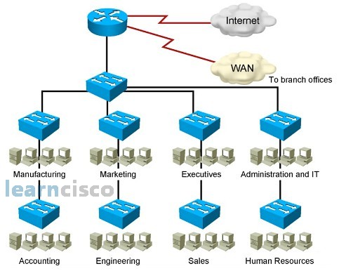
Because all the departments are in a single domain, it creates a large broadcast domain resulting in every department receiving each other’s broadcast. Also, there will be a large amount of unknown MAC addresses, and when a switch does not know how to handle a specific MAC address, it will flood to all the ports. Likewise, when the switch receives multicast traffic from different departments, it will be treated like a broadcast and flooded to all departmental ports. This excessive flooding of data traffic to every departmental port creates a management problem for the network administrator as well as making it difficult to troubleshoot the network. As the signals are heard by every other department, it also poses a security problem, too.
VLAN Overview
One of the main problems of the poorly designed network is due to excessive flooding to every departmental port. One way to separate every department broadcast signal is to have them in separate physical switches, but switches are expensive to buy, so network engineers came up with the idea of being able to separate the department broadcast signals using a logical method. The logical method allows the physical switch to be logically divided into logical segments. Each logical segment is called a virtual LAN, or VLAN for short. The objective of the VLAN is to separate each department’s broadcast signals. The VLAN gives us the ability to segment our switch into logical divisions. When dividing the switch into logical partitions, we have the flexibility to group appropriate users to the same VLANs. Although the objective of the VLAN is to separate each department’s broadcast signals, but the division is so complete that all signals, be it the unicast or broadcast signals, are isolated within each VLAN, and we consider this full isolation a security advantage.
Guidelines for Applying IP Address Space
A VLAN allows the network administrator to partition the network into departmental VLANs. But for inter-VLAN communications, we have to go through a router. Unfortunately, a router does not understand the idea of VLAN, which is a Layer 2 partition concept. For the router to route between each VLAN, a unique IP address is assigned to each VLAN so that the router can see each VLAN via the IP addresses.
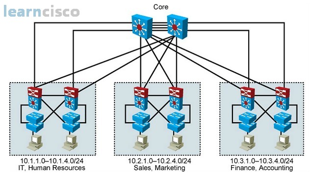
Designing VLANs for an Organization
Each VLAN in a switched network corresponds to an IP address for inter-VLAN communications. So, when planning the IP addresses, we should implement a hierarchical network addressing scheme, meaning that blocks of contiguous network addresses are reserved for and configured for devices in a specific area of the network. Some of the benefits of hierarchical addressing include the following:
- Ease of management and troubleshooting. Because the addresses are assigned in a contiguous network address, we can easily locate the problem component of the network by their IP address.
- Resulting in fewer errors or a minimization of errors. An orderly network assignment can minimize misunderstanding and duplicate address assignments.
- Reducing routing table entries. As we create more VLANs, we require more IP addresses. Because our addresses are assigned in contiguous blocks of IP addresses, we can perform route summarization to reduce the number of routing entries that are advertised through the routing protocol, thereby reducing router and bandwidth resources required.
Network Traffic Types
So how many VLANs do you need in your organization? When we are designing a VLAN network, one method of determining the number of VLANs required is by looking at the traffic type. Network management traffic may warrant an independent VLAN, as does IP telephony voice traffic. If we have dedicated multicast devices, we can also consider having a unique multicast VLAN. Normal data traffic or scavenger traffic can be considered to have different VLANs as well.
Advantages of Voice VLANs
When designing a voice network, we would assign voice traffic to a separate VLAN. The reason is because voice traffic is very delay-sensitive, and if we mix the voice and data traffic in the same VLAN, the data traffic can cause delay problems for the voice traffic. Also, having voice and data in separate VLANs allows us to implement Layer 2 VLAN QoS services to give voice traffic priority access in the switching networks. Finally, it allows the network administrator to better enforce security policies.
VLAN Operation
The Catalyst switch implements VLANs by restricting forwarding to destination ports that are in the same VLAN groups as the originating ports. So when a data frame arrives on a switch port, the switch must retransmit the frame to only ports that belong to the same VLAN group. In essence, a VLAN that is operating on the switch limits transmission of unicast, multicast, and broadcast traffic to only within each partition group called the VLAN. Traffic originating from a particular VLAN floods to only ports in the same VLAN.
VLAN Membership Modes
In this picture, we first talk about assigning data VLANs to ports.
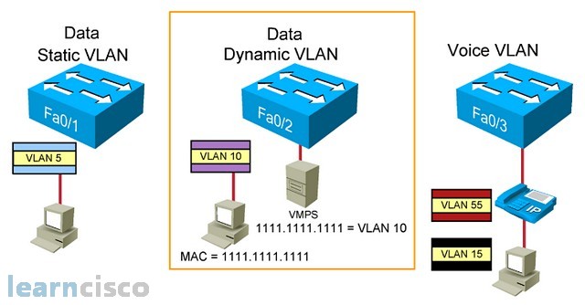
We can assign a data VLAN to the switch port via static or dynamic means, but only one data VLAN can be assigned to one port. A static data VLAN port assignment is to manually assigning a VLAN to a particular port, and it will never change once it has been assigned. A dynamic data VLAN port, on the other hand, is to temporarily assign a VLAN to a particular port depending on which user is attached to that port.
So, how does the port know which temporary VLAN to assign to this user? Well, there is a VLAN management policy server, which registers the user’s MAC address to a particular VLAN. So, when the user is attached to a dynamic data VLAN port, the port queries the VLAN management policy server with the connected user’s MAC address and determines which VLAN to temporarily assign to this port.
Now, imagine each user requires a data VLAN for their PC and a voice VLAN for their IP phone. Since we mentioned earlier, for better network control and management, we need to have data and voice VLAN having their own separate respective VLANs. The traditional idea for VLAN assignment is that one port is assigned to one VLAN, so we would need to have two switch ports for each user: one port for data VLAN and one port for voice VLAN. This would double the infrastructure switch port requirement in order to implement a Cisco IP telephony solution. The company would have to buy more Cisco switches even before considering the IP telephony deployment cost. So, Cisco engineers bend the traditional VLAN port assignment rules and allow the voice VLAN to be implemented on an existing data VLAN port, so that we can have two VLANs: the primary data VLAN and the secondary voice VLAN to be implemented together on the same port. But there are a few restrictions: you can never have two data VLANs sharing one port or two voice VLANs sharing one port. The main VLAN must always be a data VLAN and the secondary VLAN must be a voice VLAN. Also, this feature is only meant for Cisco IP telephony solution. Other company’s IP telephony solutions cannot make use of this two-VLAN-in-one-port feature.
Connecting multiple switches together
So how do you connect multiple VLAN switches together? Well, a primitive way is to have dedicated cross cables for each VLAN. But this way of connecting multiple VLAN switches together is ineffective and costly, so the network engineers came up with a more cost-effective way of connecting multiple VLAN switches together. That is through the use of a high-speed shared cable for all VLANs. We called these high-speed shared cable a trunk link.
So the more effective way of connecting multiple VLAN switches together is to use a trunk link. But there is a problem associated with having all VLANs sharing the same transportation link. When we sent data frames from different VLAN groups across the same trunk link, the switch at the other end have no means of identifying which data frames belong to which VLAN groups. So, to overcome this shared link problem, we simply assign a VLAN tag to each data frame to allow the data frames to be VLAN identifiable.

Tagging the data frames
So, tagging the Ethernet data frames helps to preserve the VLAN identity of the data frame as it is being sent through the trunk link. The solution is the same but different organizations have different means of tagging the data frame. Cisco introduced ISL trunking, which encapsulates the VLAN information around the Ethernet frame, while IEEE 802.1Q inserts the VLAN information into the existing Ethernet frame. Another difference between ISL and 802.1Q is that ISL requires all VLAN groups to be tagged with no exception, but for IEEE 802.1Q, it requires all VLANs to be tagged except one VLAN. This VLAN without a tag in 802.1Q is call native VLAN, and by default is assigned to VLAN 1.
802.1Q is the common trunking solution used in a switching network!
802.1Q Frame
802.1Q inserts the VLAN tagging information into the Ethernet frame. In the following picture, we see exactly where the VLAN tagging information is being inserted into the Ethernet frame.
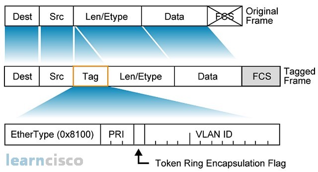
The VLAN information is inserted between the source field and the len/ethertype field. So, how does a device know that it is receiving a normal Ethernet frame or an elongated 802.1Q data frame? Well, besides inserting the VLAN information, we also insert a different piece of ethertype information. 0x8100 informs the recipients that it is receiving an 802.1Q data frame. Also, there is a priority bit in the tag to facilitate VLAN QoS.
Understanding Native VLANs
802.1Q implements the concept of native VLAN. A native VLAN is an untag 802.1Q data frame. By default, the native VLAN is assigned to VLAN 1. The reason why IEEE introduced the idea of native untagged VLAN is so that a VLAN Ethernet environment can still communicate with a non-VLAN Ethernet environment, like a hub environment, using the native VLAN.
The idea of a trunk link is to allow all VLANs to pass through, but there is a problem associated with trunk link. Now, in this scenario, all the three switches manually create their own VLANs.
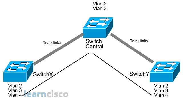
So, switch X and switch Y, due to requirements, create the VLAN 2, VLAN 3, and VLAN 4 in their switch. But the central switch only created VLAN 2 and VLAN 3. Now as you can see, switch X and switch Y are connected via trunk links across the central switch. Now, when VLAN 4 wants to send data to the VLAN 4 at the other switch, it has to go through the central switch, but this is where the problems occur. VLAN 4 information will not be able to send through the central switch because the central switch does not know what is VLAN 4. So a lot of times, people think that because it is a trunk link, the VLAN 4 information would be able to send across, but this is not the case in this scenario because the central switch is not aware of VLAN 4. Because the central switch has a different perception of all VLANs, a missing VLAN 4, it is not able to successfully facilitate VLAN 4 trunking between switch X switch Y. So, to avoid this trunking problem, we have to ensure that all of the switches have the same VLAN information. That is why Cisco introduced VLAN trunking protocol.
VTP Features
VTP stands for VLAN trunking protocol. It is a VLAN advertisement service that is advertised through all trunks links only. The objective of VTP is to synchronize the VLAN information across all switches.
There are three VTP modes:
- server
- client
- transparent
The server mode switch can create, modify, and delete VLAN information, and this information is advertised to the client switches. The client switch cannot create, modify, and delete the VLAN. It has to learn the VLAN information from the server switch. But one thing the client’s switch can do is that it can assign ports to the learned VLANs. VTP only ensures that the client’s switch learns the VLAN information. Which ports use which VLAN is not VTP’s responsibility. It is a separate task to be done locally on each switch. A transparent switch creates, modifies, and deletes VLANs for local usage, though it can pass on the server VTP information to client switches, the transparent switch uses its own local VLAN information. But, I want to stress the word “local” does not mean isolated. For example, a transparent switch created local VLAN 5 and the server switch also created VLAN 5 and sends the information to the client switch. When a broadcast is sent from the server switch VLAN 5, the client’s switch VLAN 5 would receive the broadcast. But more importantly, the transparent VLAN 5 will also receive the external VLAN 5 broadcast because the switches don’t care whether the VLAN is learned locally or externally. What matters to the switch is the VLAN number, so all three switches have VLAN number 5 regardless of where they learned the VLAN information from. As such, the VLAN 5 broadcasts will be sent to all three switches.
VTP Operation
The VTP advertisements are sent as multicast frames so that only relevant Cisco switches will proceed to decode the VTP information. Normally, VTP is advertised whenever there’s a change in VLAN information. Even if the VLAN environment has not changed, the server switch will still periodically every five minutes send out VTP advertisement to its client. So, how does the server and client synchronize to the latest VLAN information? Well they simply look at the revision number. Inside the VTP information sent, there is a revision number. When the client receives the VTP VLAN information, it will compare the revision number that it receives against what is in its own database. If the revision number is higher, the client switch will synchronize all the new VLAN information from the VTP server. Now, one thing to take note is that client replaces all the VLAN information with the current VLAN information.
Configuring VLANs and Trunks
These are the steps to configure VLANs and trunking:
- We configure the VLAN trunking protocol.
- We ensure that trunking is enabled because VTP only advertises through trunk links.
- We create the VLAN information on the server switch so that it can be disseminated to the clients.
- Manually assign the learned VLAN to the respective ports. Assigning ports to the VLAN is not the job of VTP. VTP only helps the client switches to learn VLAN information. How the client switch uses the VLAN information is not VTP’s responsibility.
VTP Configuration Guidelines
Here are some guidelines to VTP configurations. On the catalyst switch, by default, the domain name is “none” and the VTP mode is server mode. VTP pruning is enabled or disabled depending on the model of the switch in question. The password is null and it uses VTP version 2. A new switch can automatically become part of a domain once it receives an advertisement from a server. The VTP client can overwrite a VTP server if it has a higher revision number. Normally, a client will have a lower or the same revision number as the server. We are talking about a special case here, where maybe a new server switch was brought into the VTP domain to replace a faulty VTP switch. And lastly, the domain name cannot be removed once it has been assigned. The name can be changed, but it can never be removed.
802.1Q Trunking Issues
Here are some of the trunking configuration tips to avoid any problems when configuring 802.1Q trunking. We have to ensure that the native VLAN for 802.1Q trunking is the same for the entire network. Note that native VLAN is the untagged Ethernet frame. A trunk port cannot be a secure port because a secure port is meant for an access port, not a trunking port. And when you’re doing 802.1Q trunking ports in an etherchannel group, you have to ensure that they all have the same configuration.
To manually configure the port to become an 802.1Q trunk, we simply go to the respective interface and use the command switchport mode trunk.
Adding a VLAN
To add a VLAN, we first ensure that we are in the VTP server or transparent switch and not a client switch. Then, we use the command vlan 2, for example, in the global configuration mode, followed by the name command in the config vlan mode, which allows us to name the VLAN for humans’ benefit. The switch only cares about the number. To illustrate my point, the example below shows two switches configured with VLAN 2, but each has a different VLAN name. But, the switch will still see it as the same VLAN 2, as the name is not important to the switches; the number is.
SwitchA#conf t
SwitchA(config)#vlan 2
SwitchA(config-vlan)#name lab11
SwitchB#conf t
SwitchB(config)#vlan 2
SwitchB(config-vlan)#name lab22
Assigning Switch Ports to a VLAN
To assign a port or interface to a VLAN, we simply use the command switchport access vlan 2, for example, under the respective interface.
To see which ports are assigned to each VLAN, we simply use the command show vlan brief.
Our Recommended Premium CCNA Training Resources
These are the best CCNA training resources online:
Click Here to get the Cisco CCNA Gold Bootcamp, the most comprehensive and highest rated CCNA course online with a 4.8 star rating from over 30,000 public reviews. I recommend this as your primary study source to learn all the topics on the exam.

Want to take your practice tests to the next level? AlphaPreps purpose-built Cisco test engine has the largest question bank, adaptive questions, and advanced reporting which tells you exactly when you are ready to pass the real exam. Click here for your free trial.
