We will first identify the problems associated with having redundant connections means extra links between switches. It creates some associated problems which we will go in details in the subsequent lessons and how through the use of spanning tree protocol, we will create a loop free environment, which will help us avoid all these associated problems in a switch environment that have multiple links. Finally, we will learn how to make spanning tree protocol more efficient and robust through the use of our introduction of rapid spanning tree protocol as far as through the use of configuring root switch and backup root switch in the switching environment.
Interconnecting Technologies
When connecting our switching networks together, we can deploy different Ethernet technologies to provide the necessary bandwidth connectivity. So normally, for the end user connection we would use a fast Ethernet connection to the access switch. And the access switch connection to the central switch, called a distributions switch, we would choose to use gigabit Ethernet connection because many users’ fast Ethernet connection will be aggregating through this uplink. So we better ensure that we have ample bandwidth to accommodate this aggregation effect.
Then we might use a 10-gig Ethernet connection for the switch to switch backbone connections as it is going to aggregate even more traffic in the backbone. We can also use etherchannel, which allows us to combine a few low-speed links into a logical high-speed link, which will allow us to increase the bandwidth capability through load balancing internally within the etherchannel link as well as providing redundancy because the etherchannel will load balance across available links. So, should there be an outage on one of the channelized link, the load balance mechanism simply load balance with the existing links. To determine how much bandwidth we need for each link, we simply look at total amount of traffic that will flow through that link. That will give us an estimate of how much bandwidth we need.
Redundant Topology
When connecting multiple switches together, we would like to use multiple links to connect the multiple switches together, thereby creating a redundant infrastructure, which eliminates a single point of failure. But this redundant topology causes a host of feedback loop-associated problems for the switch, ranging from broadcast storm to multiple framed copies as well as MAC address database instability problems.
Here’s a quick review of how a switch handles broadcast frames.
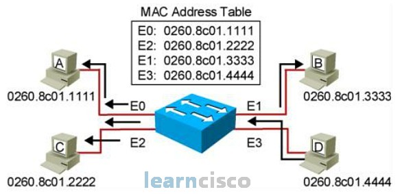
When a switch receives a broadcast frame with a destination MAC address of FFFF.FFFF.FFFF, it will not find the destination MAC address in the MAC address database. As such, the broadcast frame is treated like an unknown MAC address, which are then flooded to all ports except the originating ports.
Broadcast Storms
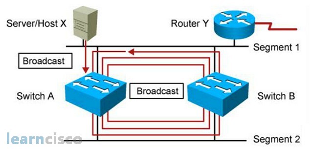
So when host X sends a broadcast into the switch A, switch A floods the broadcast to all ports except the originating port, and the broadcast gets forwarded to switch B. Switch B would do the same and will then send the broadcast back to switch A. Switch A, upon receiving the broadcast, will continue to propagate the broadcast back to switch B resulting in an endless broadcast loop. There are many of these broadcast loops happening, and we call these broadcast storms.
Multiple Frame Copies
In this example, host X sends a data frame to router Y. The data frame gets sent directly to router Y once.
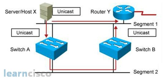
But then, switch A, upon receiving the data frame from host X, floods it to all the ports, as router Y is not a known MAC address in its MAC address database. And switch B upon receiving the data frame, floods to all the ports too. As a result, switch Y will receive an extra copy of the same data frame from the switching network. The receiver, router Y in this example, has to perform in-depth packet checking to ensure that it is not processing the same data frame.
MAC Database Instability
In this example, host X sends a unicast frame to router Y and the router Y MAC address has not been learned by either switches.
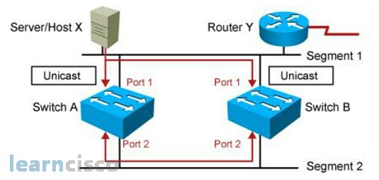
So, switch A and switch B will learn the MAC address of host X is associated with port 1. And because the router Y MAC address is not learned yet, the switch will flood the frame to all ports. In this case, you’ll flood through port 2 except port 1. Switch A and switch B will then receive this data frame via port 2, and they will think that MAC address of host X is now associated with port 2. Now in short, the reason why we have MAC address database instability is because the switch does not know how to distinguish between a direct data frame versus an indirect data frames that came through another search. So, that’s why it gets confused.
Loop Resolution with STP
Network administrator likes the idea of redundant network topology, but switches on the other hand, does not like the idea of redundant network topology because it causes a lot of feedback loop problems for the switches. So, the solution is to come up with a loop-free redundant network topology by making sure that only one link is active between switches. The extra link is temporarily disabled by temporarily blocking one of the ports so that there is no loop between the switches. The algorithm that was developed to ensure that the switching environment does not have any loops is achieved using IEEE 802.1d spanning tree protocol. PVST+ implementation will only be explained in the later slides.
So how does spanning tree protocol ensure that we have a loop-free switching environment? Well, the basic idea of spanning tree protocol is very simple. We simply turn a multilink switched network with looping problems into a hub and spoke switching network using spanning tree protocol.
How does STP works
The basic idea of spanning tree protocol is to transform a multilink switch network into a hub and spoke switch network whereby there is no loop between switches. To achieve this, the spanning tree protocol basically goes through these few steps:
- spanning tree protocol identifies a hub within the switching environment
- the non-hub switches will determine the best path to the hub
- the non-best paths are temporarily disabled so that the entire network is now hub and spoke
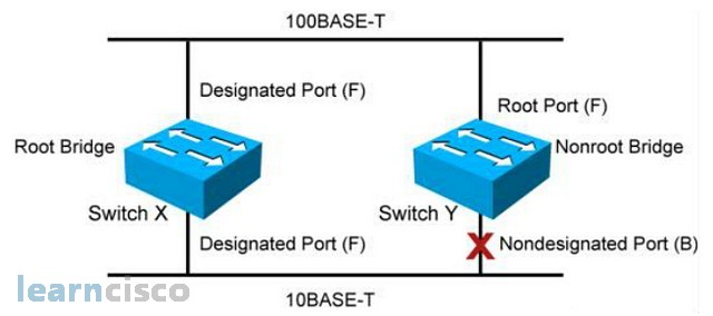
In a spanning tree environment, you can only have one root bridge per switching broadcast domain; that would be equivalent to the idea of one hub for the hub and spoke deployment. You can only have one root port per nonroot bridge. The nonroot bridge will find one best path to the root, and the best path to the root is call root port. And one designated port per segment and non designated ports are blocked and unused.
STP Root Bridge Selection
How does the switch elect a root bridge in the switching networks? Every two seconds the switches will advertise BPDU (Bridge Protocol Data Unit) to each other. The BPDU can be the switch resume that they use for root election. Inside the BPDU, there are many parameters, but the two important parameters that are used for root election is the bridge ID and the root bridge. The root bridge or the root ID is the root device name in terms of MAC address. The bridge ID is this current device priority and MAC address. The bridge priority by default is 32768 for all switches. The reason why the default priority for all switches is 32768 in the spanning tree protocol is because the bridge priority is 16 bits long, which can have a maximum number range of 65536. The middle number for this range is 32768 – not too high, not too low, right in the middle. So the middle range is 32768.
Switches advertises BPDUs every 2 seconds. During the first BPDU advertisement, every switch would advertise their bridge ID as themselves and their root bridge or the root ID as themselves too. It is upon talking, communicating with other switches, that they start learning other switches existence and slowly would elect the right switch to become the root ID. In the spanning tree protocol environment, the more desired switch would have a smaller priority or a smaller MAC address. Smaller is preferred in the spanning tree protocol. If a switch has a smaller priority, regardless of whether it has a bigger or smaller MAC address, priority overrides MAC address.
Root Port
After the spanning tree protocol has elected the root, the second step is for the nonroot bridge to find the best path to the root. Let’s start with a simple scenario on the left.
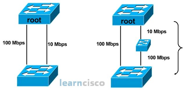
A nonroot bridge has two direct paths to the root: a 100 Mbps link and a 10 Mbps link. So the fastest way to the root would be the100 Mbps link. Therefore, the nonroot bridge will choose the 100 Mbps link as the root port, the best path to the root. But let’s look at the diagram on the right. In this scenario, the nonroot bridge has a direct 100 Mbps link to the root and a multipath multibandwidth link to the root. So, what is the bandwidth of the multipath multibandwidth link? If we try to add the two bandwidths together, we would get 110 Mbps link. But bandwidth cannot be added together so easily because bandwidth has a geographical location concept. The 10 Mbps is on top and the 100 Mbps link at the bottom, so you cannot just add the bandwidth together so easily.
Even though we would like to use the idea of bandwidth to find the fastest path to the root, trying to add bandwidth together is a problem because bandwidth cannot be easily added up together because they have geographical references. So, the spanning tree protocol engineers converted the idea of bandwidth into cost, as cost can be easily added up together. That is why we have the costing chart for different bandwidth links on the next image.

This is the costing table for the respective bandwidth link. The original IEEE costing never takes into consideration bandwidth higher that 1 gig. That is why you can see that the costing becomes stagnant at one for all links above 1 gig. So, IEEE later revised the costing to take into consideration bandwidth links higher than 1 gig.
Spanning-Tree Root Port Selection
Spanning tree protocol has a cost table that will convert the bandwidth link into the respective link cost so that the nonroot bridge can use this link cost information to find the cheapest path to the root.
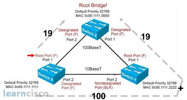
So, in this scenario, the nonroot bridge switch X has two viable paths to the root Z. It can use port 1 path or port 2 path via switch Y. By converting the bandwidth link into the appropriate costing, we can see that, if switch X were to use the port 1 path, it will cost switch X 19 cost, whereas if switch X were to use port 2 to go to the root Z, it would require 100 followed by a cost of 19, with a total of 119 cost. Switch X would then choose the lower costing to go to the root bridge. As such, switch X will elect port 1 as the root port.
Spanning tree protocol, so far, through use of BPDU, has elected switch Z as the root bridge. And by using the idea of converting bandwidth link into link cost, the nonroot bridge devices, switch X and switch Y, determined that the best path to the root with the lowest cost is port 1. Therefore, port 1 on both switches are the root port. The link between switch X and switch Y via port 2 is the non-best path link, and it has to be disabled. Now, it turns out that we only need to disable one port in order to disable the entire link. So, should switch X, port 2 be blocked or switch Y, port 2 be blocked?
To determine which port on the non-best path link to the root will be disabled first, the switches compare the root cost. The switch with the higher root cost will have its port blocked. So, in the top diagram, switch Y has a root cost of 100, which is the higher cost. As such, its port gets disabled. But what if the switches have the same root cost? In that case, the switches will compare the bridge ID and the switch with the higher bridge ID gets blocked. So, in this example, switch X has a higher MAC address; as such it port gets blocked.
In case of a cross cable connecting the same switch back to itself the higher port number will be blocked!
Describing PortFast
Whenever a switch port is enabled and connected, the switch spanning tree protocol goes through the listening and learning phases to ensure that there is no switching loop, and learns the MAC address for that switch to do data forwarding. Unfortunately, the spanning tree protocol is very naïve and checks any ports that is enabled and connected. When we connect an end-user device to the switch, which is a non-switch device, the spanning tree protocol will still take about 30 seconds to listen to any BPDUs on the port as well as learning the MAC address on the port before turning the port green to allow data to be forwarded through the port. This causes problems, as some user applications need connectivity to the network in less than 30 seconds. A well-known example was Novell clients, which needs to connect to the Novell servers in 15 seconds. It causes a lot of problems for Novell users in a switching environment. To address the problem, Cisco introduced the idea of PortFast whereby end-user ports can be manually configured to go directly to forwarding mode, bypassing the listening and learning phase.
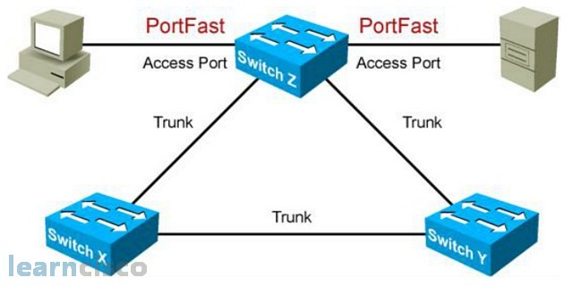
To enable PortFast, we can go to the specific interface and use the command spanning-tree portfast or we can go to the global level and use the command spanning-tree portfast default, which allows us to enable all non-trunking ports to be PortFast and to verify our PortFast configuration, we use the command show run interface, which is basically a show run command, but allows us to zoom into the interface configuration.
Advantages of EtherChannel
The way spanning tree protocol ensures a loop-free switching environment is to make sure that there is only one link between switches, and that all the switches go through the root switch. So, should you put extra physical links between the switches, those extra links would simply be disabled and not used. But, with the use of etherchannel, we can bundle or aggregate all these physical links into one logical connection, and this can fool spanning tree protocol into thinking that all these physical links are one logical link. As such, it does not proceed to disable those extra physical links. With the extra links enabled, etherchannel allows us to create a high-speed connection between the switches, where we can load balance data traffic across multiple links. Etherchannel also provides redundancy because the etherchannel mechanism would load balance across any available links. So, if you have one physical link being disabled for whatever reason, etherchannel simply load balances across the existing links.
Per VLAN Spanning-Tree (PVST)
Before we can explain PVST+, we have to explain what PVST is about. Spanning tree protocol was developed to create a loop-free physical switching environment, while VLAN is a logical switch concept. So how does spanning tree protocol operate in a virtual LAN environment? Well, the answer is it depends on how the BPDUs are being tagged in the trunking protocols. In an ISL environment, every BPDU will have their own VLAN tag, and each VLAN will only see their own VLAN BPDU. Because each VLAN sees the switching world differently, each VLAN will calculate their own spanning tree solution. We call these individual VLAN calculation their own spanning tree solution PVST, in an ISL trunking environment.
802.1Q, on the other hand, uses native VLAN to send BPDUs. So, all switches can see each other’s BPDU regardless of their VLAN distinction, resulting in a giant single spanning tree calculation for the entire switching network regardless of VLAN. We called this common spanning tree protocol.
Per VLAN Spanning-Tree Plus (PVST+)
So, PVST is a more desirable solution. But unfortunately, PVST is implemented in Cisco proprietary ISL trunking solutions. IEEE 802.1Q practices common spanning tree solution, so what Cisco did was Cisco incorporated PVST concepts into the IEEE 802.1Q solution, resulting in PVST+.
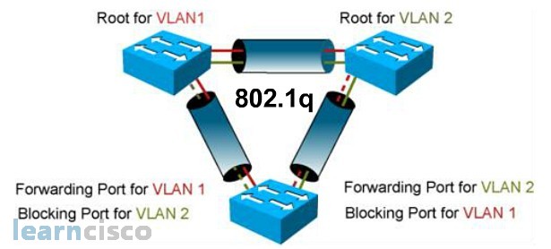
So, the idea of PVST+ is to enable a non-PVST environment, such as IEEE 802.1Q, to implement a PVST concept. So, while Cisco enhanced 802.1Q with PVST, it still has to maintain backward compatibility with IEEE 802.1Q, which uses common spanning tree methods. To do so, Cisco runs both PVST+ and CST in an 802.1Q environment. When talking to other Cisco switches, it will send VLAN tagging BPDUs to facilitate PVST+ performance. While talking to non-Cisco switches, it will send native VLAN BPDUs to those switches.
Rapid Spanning-Tree Protocol (802.1w)
The traditional spanning tree protocol, IEEE 802.1D, takes about 50 seconds to calculate and failover to a new root port should the old root port become unavailable. Now, IEEE eventually created rapid spanning tree protocol, IEEE 802.1W, to improve the performance of spanning tree protocol. One of the improvements is a better failover time, because within one spanning tree calculation, the spanning tree process would calculate the root port, which is the best cost path to the root switch, as well as determine the alternate port, which is the next best path to the root switch, so that if the current root port is not available, the switch simply failsover the to the pre-calculate alternate port, thereby cutting down the 50 seconds failover time dramatically. There are also other improvements in the rapid spanning tree protocol. One of them is to incorporate the idea of Cisco PortFast into rapid spanning tree protocol, so that end-user connections are granted immediate forwarding status without having to go through the 30-second spanning tree checking.
PVRST+ Implementation Commands
To enable PVRST+, we simply go to the global level and say spanning-tree mode rapid–pvst. Now, to verify that our spanning tree protocol is running PVRST+, we can use the command show spanning-tree vlan# or debug spanning-tree pvst+.
Our Recommended Premium CCNA Training Resources
These are the best CCNA training resources online:
Click Here to get the Cisco CCNA Gold Bootcamp, the most comprehensive and highest rated CCNA course online with a 4.8 star rating from over 30,000 public reviews. I recommend this as your primary study source to learn all the topics on the exam.

Want to take your practice tests to the next level? AlphaPreps purpose-built Cisco test engine has the largest question bank, adaptive questions, and advanced reporting which tells you exactly when you are ready to pass the real exam. Click here for your free trial.
